A barrier gate that opens in 0.3 seconds is not a motor achievement. It is a gearbox achievement.
The motor supplies rotational speed; the gearbox decides how much of that speed survives into arm movement, how much torque is left after losses, how much heat is generated per cycle, and how long the mechanism lasts before the first rebuild. Change the reduction type and you change all four — which is why two gates with identical motors, identical arms and identical controllers can behave like different product categories.
This note compares the three reduction architectures used in vehicle barriers, states where each one is genuinely the right answer, and explains why the high-speed segment converged on planetary reduction.
A barrier gate arm is a lever. A four-metre arm carrying a counterweight presents a large moment of inertia and a large static torque when it is horizontal. The drive must:
Reduction ratio converts the motor’s high speed and modest torque into the arm’s low speed and high torque. What distinguishes the architectures is not the ratio they can achieve — all three reach the ratios a barrier needs — but the mechanism by which they transmit force, and therefore what wears out.
| Property | Worm | Spur / helical | Planetary |
|---|---|---|---|
| Contact between teeth | Sliding | Rolling | Rolling |
| Single-stage ratio | 5:1 to 100:1 | 2:1 to 8:1 | 3:1 to 12:1 |
| Efficiency per stage | 40–70% | 95–97% | 96–97% |
| Self-locking without a brake | Yes (low lead angle) | No | No |
| Heat generated at high cycle rates | High | Low | Low |
| Noise at arm speed | Moderate | High | Low |
| Radial load on the motor shaft | High | Moderate | Very low |
| Envelope for a 100:1 ratio | Compact | Long, multi-stage | Compact, coaxial |
| Backlash after 1 million cycles | Grows quickly | Moderate | Small, adjustable by preload |
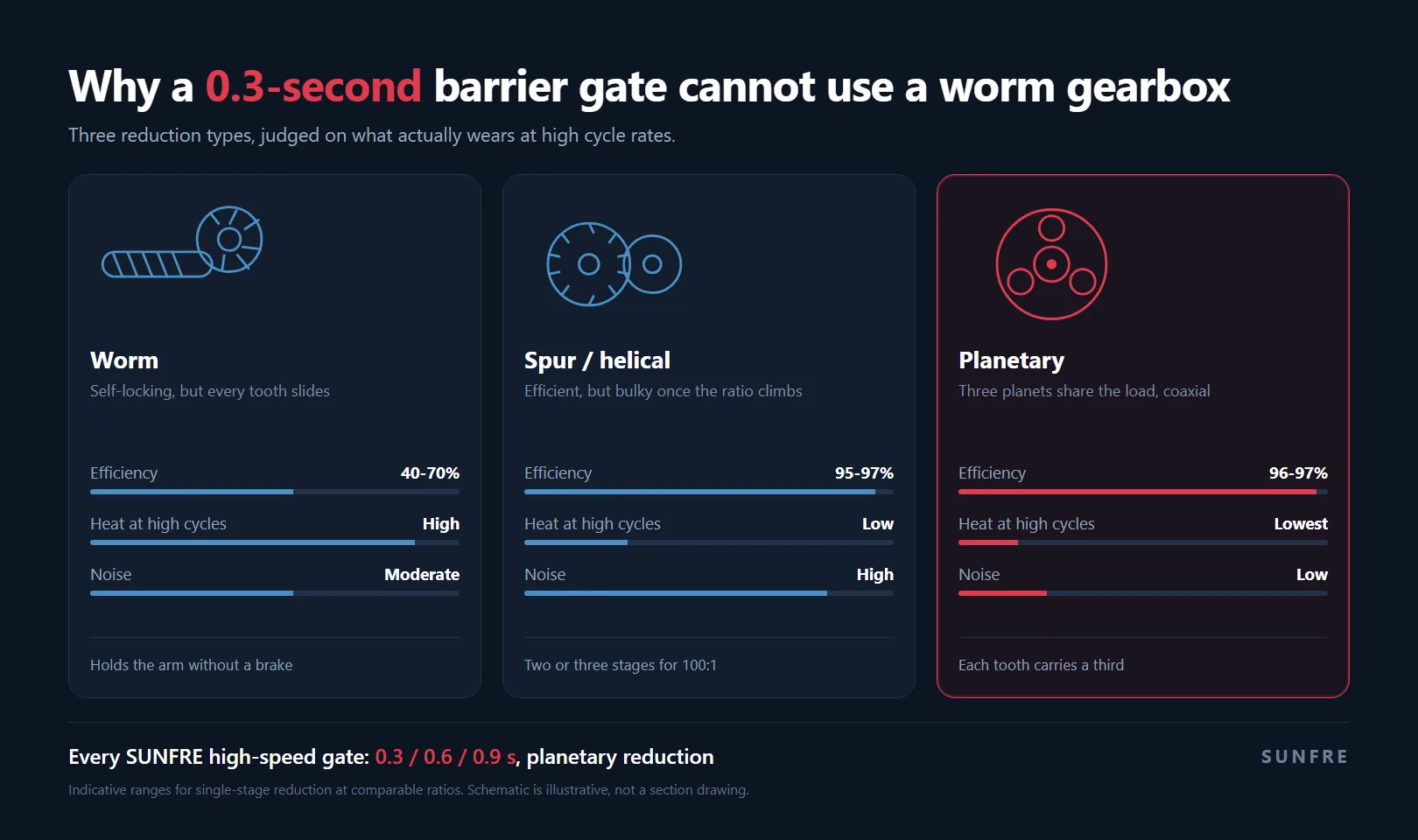
This is a comparison of architectures, not of suppliers. Every point applies to any manufacturer building with these parts.
It would be dishonest to present the worm gear as obsolete. It has two properties that still matter:
It self-locks. At a low lead angle the worm cannot be driven backwards by the load. A barrier with a worm drive holds its arm in any position with the motor de-energised and no brake at all. For a slow, heavy arm on a low-traffic site — a residential compound entrance, a warehouse gate used a few dozen times a day — this is an elegant and inexpensive solution.
It achieves a large ratio in one stage. A 60:1 reduction from a single pair is compact and cheap to manufacture, which is why it dominates the low-cost segment of the market.
The limitation is not the ratio. It is the contact geometry.
In a worm pair, the tooth of the wheel slides against the thread of the worm. Sliding friction is the entire transmission principle. That has three consequences that scale with cycle count:
None of this makes a worm gate unsafe. It makes it unsuitable where the duty cycle is measured in thousands of vehicles per day — which is precisely the segment where sub-second opening is requested in the first place.
A planetary set distributes the load across three or more planet gears orbiting between a sun gear and a ring gear. Three properties follow directly from that geometry.
Load sharing. Each planet carries roughly a third of the total torque at any instant. Tooth stress — and therefore wear rate — drops by the same factor compared with a single mesh transmitting the same load. This is the single most important reason the architecture survives high cycle counts.
Coaxial layout. Input and output share an axis. The gearbox sits inside the housing behind the motor instead of beside it, which keeps the enclosure compact and the arm pivot close to the drive.
Low radial load. Because the planets surround the sun symmetrically, the net radial force on the motor shaft is close to zero. Bearings run cooler and last longer, and the motor can be smaller for the same output torque.
The cost is manufacturing precision: planet carriers, ring gears and preload adjustment are harder to make than a worm pair. That cost is why planetary drives appear in the high-speed segment rather than across the whole market.
This is the architecture used on every SUNFRE high-speed barrier gate, at 0.3, 0.6 and 0.9 seconds, with opening and closing times adjustable up to 6 seconds where a site needs a slower, gentler arm.
Traffic determines which mechanism is appropriate far more than the requested opening time does. Rated mechanism life of 5,000,000 cycles, divided by real traffic — one open and one close per vehicle:
| Vehicles per day | Cycles per year | Rated life in years |
|---|---|---|
| 300 | 109,500 | 45.7 |
| 1,000 | 365,000 | 13.7 |
| 2,000 | 730,000 | 6.8 |
| 5,000 | 1,825,000 | 2.7 |
| 8,000 | 2,920,000 | 1.7 |
Two honest readings of that table:
Below about 1,500 vehicles a day, the mechanism is not the constraint. Five million cycles is a decade of service. Money is better spent on sensors, integration and civil works than on a heavier drive.
Above about 4,000 vehicles a day, the arm becomes a consumable. A 0.3-second mechanism on an 8,000-vehicle toll lane has a rated life under two years. That lane needs the heavy-duty mechanism and a planned replacement interval — not the fastest arm on the price list.
MTBF is also not service life. It is the mean interval between mechanism failures on a test bench, not a warranty period, and it says nothing about springs, tyres, sensors or arms, which are replaced far sooner.
Can a worm-drive gate open in 0.3 seconds? It can be built to try, and it will not hold up. The limiting factor is thermal and wear, not the motor: at that speed the mesh generates heat faster than the housing can shed it, and the thread wears at a rate that destroys the position accuracy the safety system depends on.
Does a planetary gearbox need a brake? Yes. Planetary reduction is not self-locking, so the arm is held by a service brake or by the motor’s holding torque. That is a deliberate trade: the brake is a known, replaceable wear item, whereas a self-locking worm hides its wear inside the mesh.
Is a belt or chain drive an alternative? For low-speed, low-duty barriers, yes — they are cheap and quiet. They also stretch, need tensioning, and are unsuitable for sub-second reversal duty.
Does gearbox type affect anti-crush performance? Indirectly, and significantly. Servo torque feedback can only reverse the arm quickly if the drivetrain has low backlash and low inertia. A worn worm mesh adds hesitation between the current spike and the arm actually reversing — which is exactly the interval that matters.
Are high-speed gates louder? Not necessarily. Planetary sets run quieter than helical pairs at the same speed because the load is shared across several meshes rather than concentrated in one. Noise in the high-speed segment usually comes from the arm and the housing, not the gears.
The practical rule is straightforward: select the drive by vehicles per hour, then select the opening time the operator actually needs, then verify the mechanism’s rated life at that traffic. Buying speed when the lane needed duty is the most common specification error in this product category — and the most expensive to correct, because it only becomes visible after the mechanism is on a pole.
For the wider selection logic — arm length, lane width, sensor stack and integration — see the barrier gates guide. For the drive comparison in more depth, see AC vs BLDC vs DC servo motors. For the safety layer that depends on drivetrain precision, see barrier gate anti-crush.
To specify a lane, send the lane width, the traffic count, the site conditions and the integration requirement. SUNFRE quotes per project rather than publishing list prices, because those four inputs determine the configuration. Certificates are available on request.
—
Figures in this article are indicative ranges for single-stage reduction at comparable ratios, and the cycle-life table assumes one open and one close per vehicle. Rated life is a bench MTBF, not a warranty period.
